I.5. Control Ports

H1, H2, H3, H4, H5, and H6 are the ports for control inputs. We can use these ports to read potentiometers, selector switches, buttons, or control voltage.
Buttons connection to the control ports has been described in the previous section (I.4). See Figure 2 (part C and D) for the quick reference.
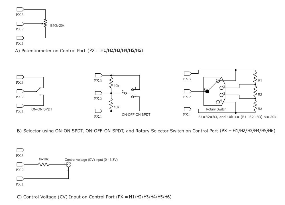
Potentiometer can be connected directly to the control port, as show in the Figure 3 (part A). The recommended value for the potentiometer is between 10k to 20k (linear). Pin 1 and pin 3 connections between port and potentiometer are interchangeable because the rotation direction can be inverted in the software.
Selector switches can be implemented using 2-position ON-ON SPDT switch, 3-position ON-OFF-ON switch, or multi-position rotary selector switch (see Figure 3 part B). For n-position rotary switch, a number of n-1 resistors (all with the same values) are arranged as multi-tap voltage divider. The total series resistance (R1+R2+.. +Rn-1) of this voltage divider is recommended to be around 10k-20k.
Control voltage (CV) input can be connected to the control port at pin 1 (GND) and pin 2 through a 1k-10k resistor (see Figure 3 part C). This resistor is employed to limit the injection current when the input is accidentally getting higher than 3.3V.