High Voltage 220V AC Lamp Flasher Using 555 IC

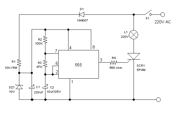
220V AC Flasher Lamp with 555 IC Schematic Diagram
Similar with previous high voltage flip-flop circuit, this circuit controls high voltage (powerline) bulbs (220V AC). Instead of using transistors, this circuit uses NE555 integrated circuit, a very popular chip for timer or oscillator application. The required low voltage supply for 555 IC is provided by direct converter, made up by D1, R1, DZ1, and C1. This low voltage is set at 10V by Zener diode DZ1, and the ripple is filtered by C1 capacitor. Please be warned that all of the wiring is not isolated from powerline voltage, so don’t touch any connection while plugged into the power line. The flashing period is determined by R2, R3, and C2. The simplest thing to change the period is by replacing C2 capacitor with different value, smaller for faster flashing period, and bigger for slower. The power of the used bulb will be 50% of the rated power since the SCR will conduct only on its half cycle. See the video of the working circuit in the Youtube video channel below. In the video, you can see the R1 resistor is constructed by paralleling many low wattage resistors to get higher rating. Beware of high voltage dangerous shock, don’t forget the precaution!