Adjustable 1-30V Laboratory Power Supply Uses Switching and Digital Control Technology
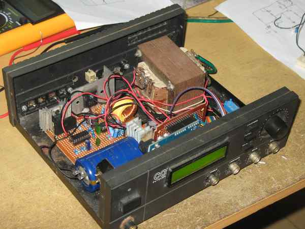
Figure 1. Assembled Hamuro Programmable 1-30V Laboratory Power Supply
Laboratory Power Supply Requirement
Power supply for electronic circuit experiments need some special features. Ideally we need a precise, stable, reliable, and easy voltage adjustment power supply for working convenience. Being precise means that our power supply should give a voltage as close as possible to the desired value. A stable (low ripple) and very consistent (insensitive to operating time and ambient temperature drift) is probably what we define as stable. Reliable might mean that the power supply will keep working properly and safely although some failures happen its usage. Voltage adjustment should be provided to make it flexible for various circuit with various voltage requirements.
Wide Range Adjustment, Stability, and Efficiency
High efficiency is not really crucial for research activity, but it’s a good benefit if we can go green by saving energy. For good stability, a linear voltage regulator will be cheap and easy solution for small range voltage adjustment, but it’ll be very inefficient for for wider range. If we can accept some ripple caused by switching process, then a switching regulator will be a great solution for wide range adjustment while maintaining good efficiency. With this pros and cons, let’s design our power supply with switching regulator technology.
Switching Regulator Circuit
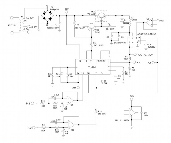
The switching controller is designed using TL494 integrated circuit. The schematic diagram of the circuit is shown in Figure 2. TL494 is a low cost complete solution for switching controller. It has sawtooth oscillator, PWM modulator, error amplifier, 5V voltage reference, and the transistor driver.
Figure 2. Circuit’s Schematic Diagram of Hamuro 1-30V Variable Switching Regulator
The schematic diagram is based on the design case presented in the reference [1], Designing Switching Voltage Regulators With the TL494, Texas Instruments Application Report. Here we modify some part, replace current sensing to use Hall effect sensor chip ACS712ELCTR-3/5 instead of sensing resistor. We also add low pass filter for control voltage, both for controlling the voltage (P.2) and the current limit (P.1). We add this low pass filter since we want to control this input using PWM signal from micro controller, the cheapest solution to get a DAC function.
Soft Start Control
At the first time the power supply is turned on, the voltage is increased slowly to avoid current rush. TL494 is configured to provide this feature, and can be adjusted by selecting proper C6 value (2.2uF), which gives rise time about 40-50 PWM pulse cycle.
Voltage Feedback
The output voltage is regulated by switching on and off TR1 and TR2, and this is done by a fixed frequency PWM generated by TL494, which is configured to produce around 40kHz pulse by setting C5 and R6 with the shown values. The main PWM control is done by comparing the output voltage and the control voltage. The output voltage (after going through Hall effect current sensing chip) is first divided by R4 and R5 voltage divider. 1 to 30V on the output will produce 0.15 to 4.5V. This voltage is the compared with control voltage from U2 output. When the voltage is lower than the control voltage then the TL494 will produce wider pulse until the voltage between pin 1 and pin 2 of TL494 is equal. By this feedback mechanism, we can control the output voltage to produce 1-30V by controlling the duty cycle of P.2 PWM input to make 0.15 to 4.5V variation on U2 output.
Current Limiter
One important requirement for lab power supply is overload and short circuit protection, since circuit failure frequently happen when testing experimental circuit. The power supply should be tolerant of overload and short circuit condition. This function is provided by comparing voltages between pin 15 and 16 of TL494. If voltage at pin 16 is higher than voltage at pin 15 then PWM pulse will be turned off. Since pin 16 is connected to the output of current sensing chip, this circuitry will prevent the overload or short current from damaging the system. We don’t need a voltage divider since both current sensor output and the comparator input has the same voltage range: 0-5V. The current sensor IC ACS712ELCTR need +5V supply voltage, and the best source comes from 5V reference produced by TL494 at pin 14, so we amplify this reference voltage using one op-amp section of LM324 (U3) to enable higher current drive.
Transformer Selection
The main transformer is a regular transformer for powerline adapter. Most of transformer voltage and amperage rating is overspecified to give impression of higher performance. Some testing on commercial on local store in our city (Yogyakarta, Indonesia) show that they specify the maximum amperage on the overloaded voltage condition which is lower than what is specified. For 5A 30V specification as shown in the schematic diagram, we can expect a 36 VDC at 10000uF capacitor when there’s no load (0A), and a 30V at 5A current. When we count only the average voltage value then it looks like we can maximize it to produce stable 30V at 5A load current, but this is not true since there actually big voltage ripple swinging under and over 30V. Stabilizing the over voltage by cutting the magnitude into 30V is easy, but compensating the under voltage is not, even with such high capacity capacitor. Our testing show that using a 30V 5A transformer, a stable 30V output can be produced when the load current is kept under 1A, and a 10V stable output can be produced when the load current is kept under 3A. You can see the transformer has second winding of 9V 0.5A output, and it will be used to power the micro controller module to provide key switch and LCD user interface. If you can’t find separated secondary winding in one transformer then you can use small separated transformer around 300mA (9-12VAC).
Digital Control for Easy Adjustment
In today’s electronics, micro controller becomes cheaper and cheaper, replacing many analog functions. It will be used in the user interface design of our power supply circuit. We can say our system as hybrid, since the switching control is still done using analog integrated circuit. Using digital system for control and display enable us to conveniently operate this circuit. We will be presenting the micro controller system (the schematic diagram, the program code) for this power supply in the second part of this article: Digital Control for Laboratory Power Supply Using Arduino.
You can show the assembled power supply in action on our Youtube channel below, just watch before you make it!
References
- Designing Switching Voltage Regulators With the TL494, Texas Instruments Application Report, December 2003 – Revised September 2011.


with c5 and r6 from diagram. the frecuency is not 40 khz
I’m building up a copy of this circuit, and am finding a few things (so far):
-Ct and Rt values listed give a f(osc) of ~4kHz. I assume a simple typo, and a missing decimal spot or something off-by-ten. A 1nF cap instead of 10nF works.
-R1/R3 don’t provide enough voltage to trigger a BD140. Dropping R3 to 1k fixes.
-I increased R4/R5 by a factor of 10 to reduce heat produced
-The LM324 (at least, the one I’m using) can’t go down below about 500mV. This limits the lower voltage and current limit. I’m going to try adding a pulldown resistor on the outputs as suggested in TI’s design guide for the ‘324: https://www.ti.com/lit/ds/symlink/tl494.pdf?ts=1622775946339