Step-Up DC-DC Converter Circuit for Laptop Charger/Adapter, Convert 12V(9-14) to 19V(16-21V)
Step-Up Converter 12 to 19V for Laptop
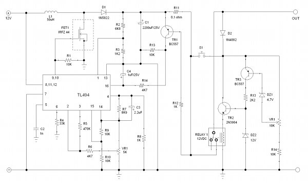
This DC-to-DC converter circuit enables automotive lead-acid battery to power your laptops/notebooks, converting 12VDC to 19VDC with good efficiency since it uses switching technology. I designed this circuit to make power backup for small home office to provide eight hours backup for three notebooks. The input voltage range is 9V to 15V, which is suitable for various battery condition in automotive environment. The output voltage can be adjusted from about 16V to 21V, which cover almost any brand of notebooks. Figure 1. below show the schematic diagram of the circuit.

Figure 1. Circuit’s Schematic Diagram of Hamuro’s Step Up DC-to-DC Converter 12V to 19V for Laptop
The Switching Controller
The circuit uses TL494 switching controller as the main control of the stepping up process. The output of TL494’s internal transistors directly drive an N-channel Power MOSFET IRFZ44. This power MOSFET, together with the inductor and D1 diode, is configured as boost converter. The switching controller will produce a pulse width modulated (PWM) signal that drive the Power MOSFET which regulate the voltage output to have a stable level although the load and the supply voltage varies. The voltage output can be adjusted by VR1 variable resistor (trimmer potentiometer), ranging from 16 to 21V (use a voltmeter to adjust this).
Current Limiter
A high side current sensing circuitry, the same as described in our previous current sensing article, is build around TR1 transistor and R11 -R12 resistors. Since TR1 will be activated to limit the current when the voltage across R11 rise above 0.6V, we can select this resistor (R11) to specify the level of current limiting. Using 0.1 ohm as shown in the schematic diagram, a 6A current will produce 0.6V across R11 to activate the limiter. This limit point is not so accurate since the bias voltage of TR1 base depend on its temperature and its tolerance, so we have to experiment to get the best result. A 0.2 ohm value is recommended as the starting value to set about 3A limit. Please be warn if we set the limit at 6A then D1 will be overheated and we should replace the diode with higher amperage rating. The schematic diagram show 0.1 ohm resistor since our experiment result in 2.5A limiting instead of 6A, far from formulated by the theory.
Short Circuit Protection
The nature of boost converter topology has no protection of short circuit, even though it has current limiter circuitry. Although the TL494 switching controller can totally turn off the MOSFET all the time (active factor/duty cycle=0), but the inductor is still being shorted to ground via the diode and the (shorted) load. Here a short protection circuitry is added, which is built around TR2 and TR3 transistors, relay, and some diodes and resistors. It has different topology than our previous short circuit protection since this application should cover wide range of output voltage level, from 16 to 21V. This circuit works by detecting voltage drop to deactivate an electromechanical relay, and should be calibrated by adjusting the 10k variable resistor. Adjust this variable resistor to trip off the output if the voltage drops 2V below the output setting.
hey … I tried this but it didn’t work … I even gave double check for everything but it still didn’t work …. any advices ?
You can measure the voltage of every point in respect to ground, then I might be help you to find the problem.
Hamuro, is there a higher resolution version of the schematic? It’s hard to make out some of the component values/part numbers.